La livraison gratuite de plus de 1000DH pour les particuliers
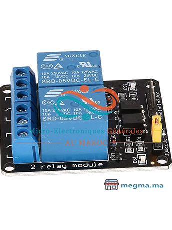
Module relais 2 Canaux 5V
Le prix initial était : 30.00 د.م..28.00 د.م.Le prix actuel est : 28.00 د.م..
Le module relais 2 canaux 5V est une solution simple et pratique pour commuter 2 relais de puissance directement à partir d’une carte Arduino – ESP – Raspberry ou compatible.
38 en stock
Tutorial: Interface 2 Channel Relay Module with Arduino (Module Relais 2 canaux 5V)
Sometimes you want your Arduino to control AC powered devices like lamps, fans or other household devices. But because the Arduino operates at 5 volts, it cannot directly control these higher voltage devices.
That’s where the relay module comes in. You can use a relay module to control the AC mains and Arduino to control the relay.
This tutorial walks you through how to setup the relay to switch on a lamp or other device, but let’s begin with a short introduction into relays.
How Do Relays Work?
Same us single relay channel – Link
Output Terminal Blocks
We have three channels per relay broken out to blue screw pin terminals. The channels are labeled for their function: common (COM), normally closed (NC), and normally open (NO)
The names explain the state of the channel with relation to the switch at rest.
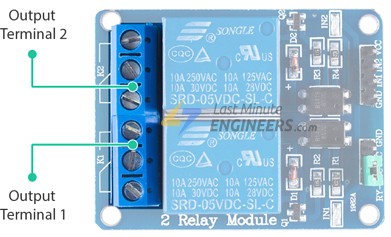
COM (Common): This is the pin you should connect to the signal (mains electricity in our case) you are planning to switch.
NC (Normally Closed): A normally closed configuration is used when you want to turn off the relay by default. In this configuration the relay is always closed and remains closed until you send a signal from the Arduino to the relay module to open the circuit.
NO (Normally Open): A normally open configuration works the other way in which the relay is always open until you send a signal from the Arduino to the relay module to close the circuit.
Control Pins
On the other side of the module, there are four pins – a Ground pin and a VCC pin to power the module and two input pins IN1 and IN2 to control the relay.
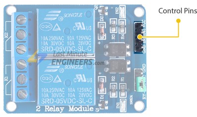
The input pins are active low, meaning the relay will be activated when you pull the pin LOW and it will become inactive when you pull the pin HIGH.
Power Supply Selection Jumper
Notice that the module has a jumper cap connecting the VCC and JD-VCC pins.
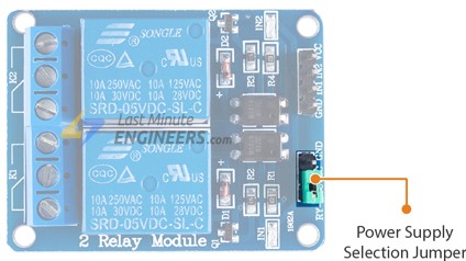
The jumper cap allows you to choose whether the circuit is physically connected to the Arduino.
When the jumper is in place, the electromagnet of the relay is directly powered from the Arduino. In this case the relay module and the Arduino are not physically isolated from each other.
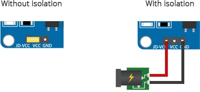
Without the jumper cap, you have to provide an independent power source to power the electromagnet of the relay through the JD-VCC pin. This configuration physically isolates the relay module from the Arduino with the help of the built-in optocoupler.
Control Pins:
VCC pin supplies power to the built-in optocoupler and optionally to the electromagnet of the relay (if you keep the jumper in place)
GND is the common Ground connection.
IN1 & IN2 pins are used to control the relay. These are active low pins, meaning the relay will be activated when you pull the pin LOW and it will become inactive when you pull the pin HIGH.
Power Supply Selection Pins:
JD-VCC supplies power to the electromagnet of the relay. When the jumper is in place, it takes power from the Arduino’s 5V line. Without the jumper cap, you have to connect it to an independent power source.
VCC With the jumper cap on, this pin is shorted to the JD-VCC pin. If you remove the jumper, keep this pin unconnected.
GND is the common Ground connection.
Output Terminals:
COM pin is connected to the signal you are planning to switch.
NC pin is connected to the COM pin by default, unless you send a signal from the Arduino to the relay module to break the connection.
NO pin is open by default, unless you send a signal from the Arduino to the relay module to make the connection.
Wiring Relay 2 Channel Module with Arduino UNO
Now that we know everything about the relay module, it is time to put it to use!
Let’s set up our relay module to switch on a lamp.
Start by connecting VCC pin on the module to 5V on the Arduino and GND pin to ground. Connect the digital pin #6 to the IN1 input pin for controlling the first relay.
You’ll also need to place the relay module in line with the AC powered device (lamp in our case) you’re attempting to control. You’ll have to cut your live AC line and connect one end of the cut wire (coming from the wall) to COM and the other to NC or NO depending on what you want your device’s resting state to be.
If your AC device is going to be off for most of the time, and you occasionally want to turn it on, you should connect the other to NO. Connect to NC if the device will be on for most of the time.
For this project we want our lamp to be off in resting state and illuminated when we activate the relay, so we will put one end in COM and the other in NO.
The following illustration shows the wiring.
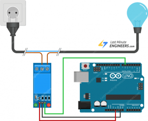
In the above wiring diagram we have kept the jumper in place, due to which the electromagnet of the relay will be driven directly from the Arduino. In this case the relay module and the Arduino will not be physically isolated from each other.
If you want to keep them isolated then you have to provide an independent power supply through the JD-VCC pin.
Arduino Code
Now that our hardware is all set up, let’s take a look at the code that turns the lamp on.
Here’s the simple code that will turn on the lamp for 3 seconds and keep it off for the next 3 seconds. Plus d’information visite notre page Facebook.
/*

* Réaliser par Micro-Electroniques Générales au Maroc
* Visite notre site megma.ma

*/
int RelayPin = 6;

void setup() {
	// Set RelayPin as an output pin
	pinMode(RelayPin, OUTPUT);
}

void loop() {
	// Let's turn on the relay...
	digitalWrite(RelayPin, LOW);
	delay(3000);

	// Let's turn off the relay...
	digitalWrite(RelayPin, HIGH);
	delay(3000);
}
Code Explanation:
Controlling a relay module with the Arduino is as simple as controlling an LED. The sketch starts by declaring the pin to which input pin of relay module is connected.
int RelayPin = 6;In the setup function, we define that pin as being output.
pinMode(RelayPin, OUTPUT);Now in the loop function, we turn the device ON/OFF by pulling relay pin LOW/HIGH respectively.
digitalWrite(RelayPin, LOW) pulls the pin LOW whereas digitalWrite(RelayPin, HIGH) pulls the pin HIGH.
digitalWrite(RelayPin, LOW);
delay(3000);

digitalWrite(RelayPin, HIGH);
delay(3000);





Avis
Il n’y a pas encore d’avis.